--- Welcome to RFsignal.eu ---
Reference Dipole Antenna for ISM Band (868 MHz)
This short article deals with a dipole antenna for ISM (Industrial, Scientific and Medical) band. This band can be used for sensor networks which have been receiving great interest nowadays (IoT - Internet of Things). There are many applications where the sensors must have small dimensions and therefore the antennas inside such devices are highly miniaturized. The less the space available and the more components are placed nearby the antenna, the more the radiation of the antenna is affected.
This problem is probably not so critical for our home projects but it is still nice to know how your board with a temperature sensor and a small antenna performs and eventually to increase the range of the sensor by optimizing the distribution of the components etc. Therefore I made a reference dipole with an integrated balun that I can use for my tests allowing me to compare several designs.
I found an article Evaluation of Polarization Diversity Antenna for Wireless Communication Applications where my antenna came from. I changed the resonant frequency of the dipole and modified the ground plane. The results with the dimensions are as follows:

Radiation pattern

Radiation pattern - cross polarization

Dimensions - top view

Dimensions - bottom view

Radiation pattern - H plane

S11 parameter (-Return Loss)
Practical realisation, PCB is made of FR-4 - 1.6 mm

FT8 Monitoring Station with SDR and Raspberry Pi 3B
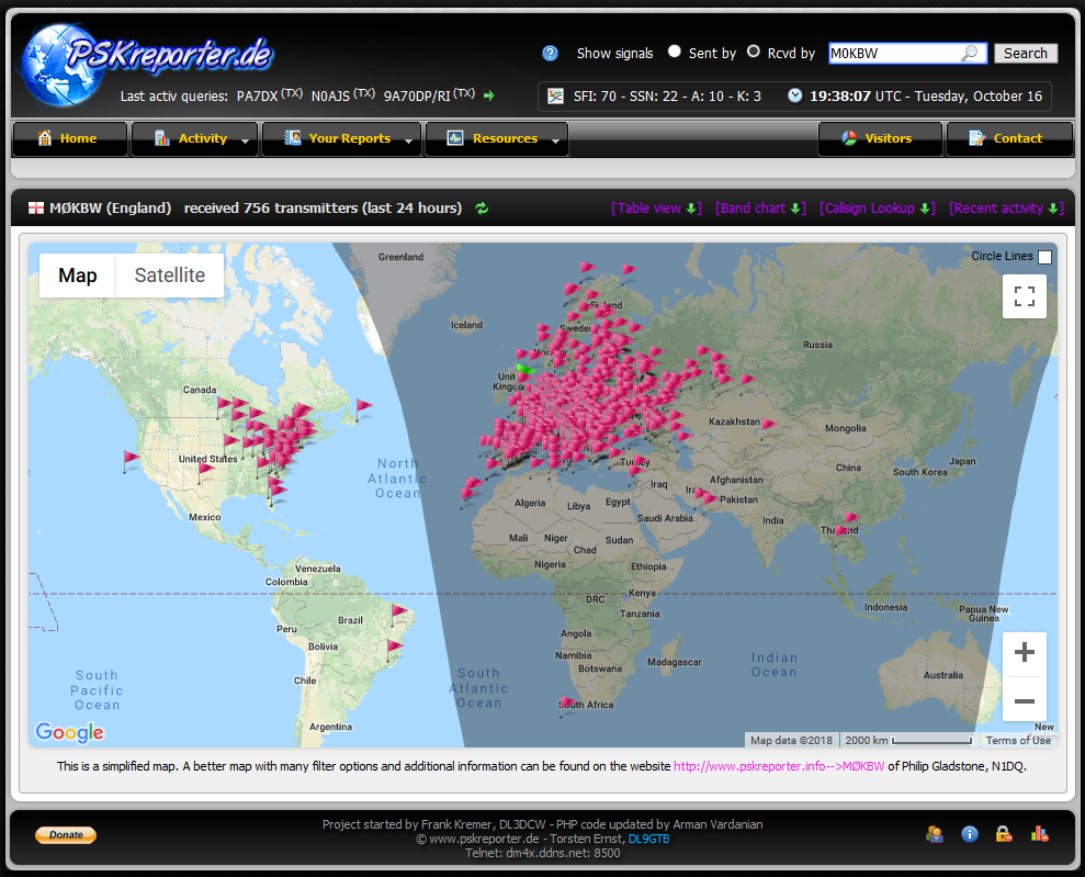
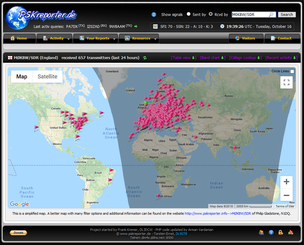
FT8 is a digital mode, invented by Joe Taylor K1JT, that has become very popular these days. A lot of people talked about it in both possitive and negative ways, so I decided to make my own opinion. When I was playing with WSJT-X software, I found that there is a possibility to upload the decoded stations to a server where all the contacts are shown in a map. I found this exciting, so I connected my Raspberry Pi to the transceiver (TRX) and watched the propagation for several days. Unfortunately, the power consuption of the TRX is quite high, so I had the idea to try that with my software defined radio (SDR) HackRF. I used GQRX software in combination with WSJT-X and Pulse Audio Volume Control (pavucontrol) for mixing the audio signals (virtual audio cable). I noticed that there was a problem with reception not being reliable. Firstly I thought that it was caused by a weak power supply, so I replaced my DC addapter with a laboratory power supply. After some tests I noticed that the main chip on Raspberry Pi was getting very hot. Therefore, I ordered an active heat sink that keeps Raspberry Pi cold and it made a great difference. Now I can run the monitoring station 24/7 without any problems. Furthermore, I tried to compare the reception of my TS-590SG with HackRF SDR. TS-590SG has a power divider already built in, so I could use it for splitting the signals comming from my indoor antenna. To be fair, by connecting the SDR to the TRX, the noise level of the TRX increased a bit. On the other hand, I could not hear this effect when the antenna was connected as the noise floor was much higher. The results are shown below the text. It can be seen that they do not differ that much. My HF transceiver received 756 transmitters, 1691 reports and 57 countries in 24 hours in comparison to the SDR where 657 transmitters, 1370 reports and 54 countries were decoded. It seems that SDR in combination with Raspberry Pi works well. As I want to keep HackRF for other tests, I decided to buy a cheeper RTL-SDR for this automatic monitoring station. (Please see the results below.)


SDR + Raspberry Pi 3B with a heat sink
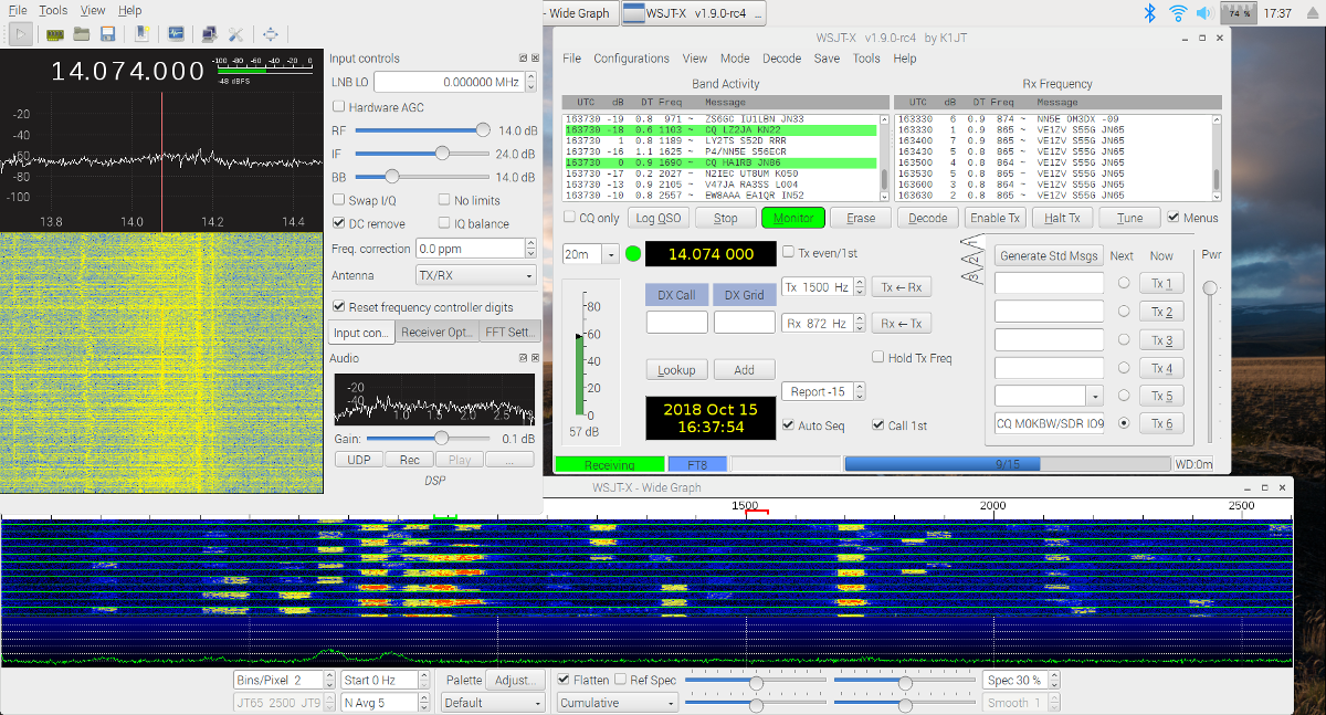
GQRX + WSJT-X running on Rasberry Pi 3B
Map, reception at 14.074 MHz, TS-590SG
Map, reception at 14.074 MHz, HackRF
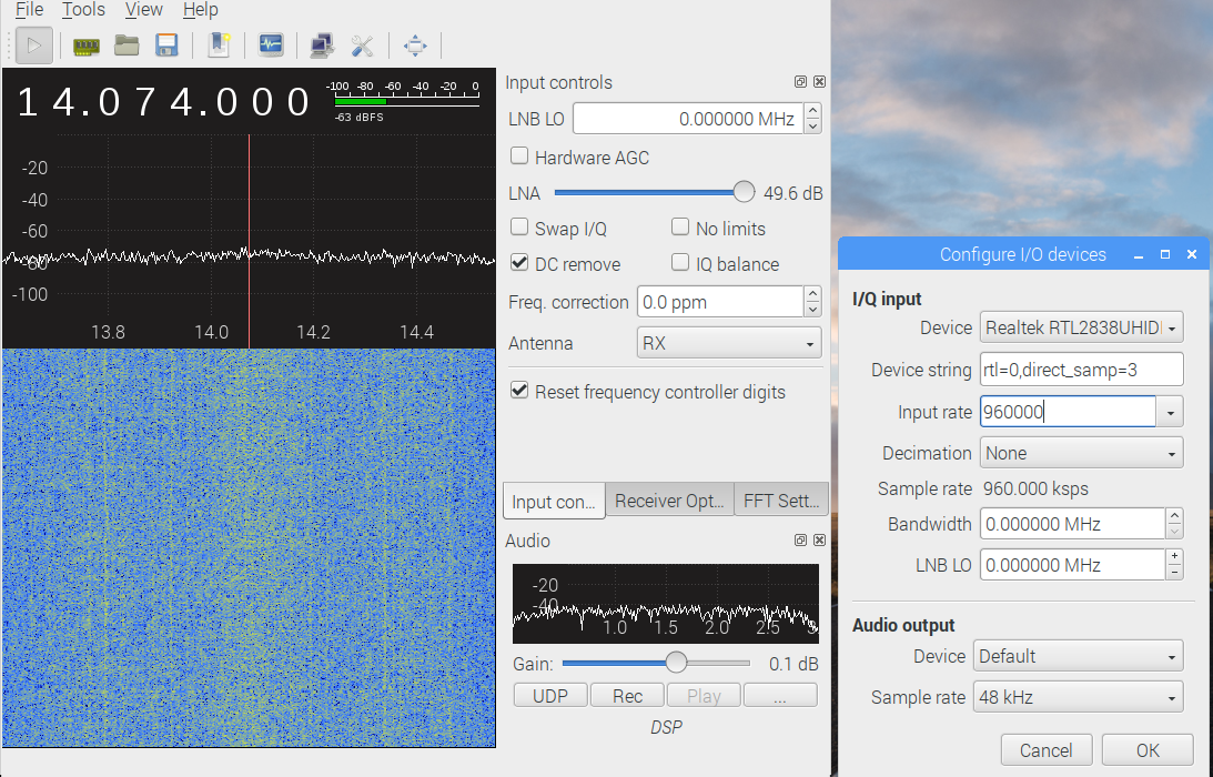
My new RTL-SDR (version no. 3) has been delivered. GQRX software does not allow to receive signals below 24 MHz in combination with RTL-SDR until a direct sampling mode is activated. I found a message of Thomas KC3JVH (link) that this can be done by writing direct_samp=3 into the device string in the config window (see the screenshot below), so no up-converter is required for HF reception with this particular dongle. I compared RTL-SDR in the same way as HackRF with the reference transceiver TS-590SG. TS-590SG received 771 transmitters, 1742 reports and 56 countries in 24 hours in comparison to RTL-SDR where 728 transmitters, 1611 reports and 56 countries were decoded. I am very happy with that.

Links:
https://pskreporter.info/pskmap?callsign=M0KBW
https://www.pskreporter.de/?s_type=rcvdby&call=M0KBW&search=Search
Narda Power Divider 1-2 GHz, Model 4312-2
S11 and S21 measurements of a power divider (Narda 1-2 GHz, model 4312-2) are presented in the following figures. A VNA (pocketVNA) for S11 measurements and a spectrum analyser with tracking generator for S21 measurements were used. As can be seen the S11 results are a bit noisy therefore I interpolated the measured data with a short script written in Python for easier reading. It can be seen that the divider performs really well.

S11 Measurements:


S21 Measurements:


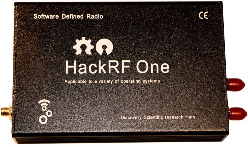
HackRF One: EMI Shield + Aluminum Enclosure
HackRF One is a software-defined radio capable of transmission or reception of radio signals from 1 MHz to 6 GHz. I bought this radio for my tests more than one year ago. It came in a plastic enclosure and as it can be seen in the following picture, it was not RF shielded even though the PCB was prepared for it. Therefore I decided to buy an RF EMI shield and an aluminum enclosure. Furtheremore, the shield came also with a PCB testpoint and a 20 position header that I added as well.


QCX CW Transceiver Kit
Last weekend I finished my new transceiver for my SOTA (Summit On The Air) activations. This is a single-band TRX with power of 2 - 3 W by QRP Labs. I chose to build one for my favourite HF band 7 MHz.

 |
 |
|
|
|
I have performed a quick measurement of the output power measuring the pak-to-peak voltage across a 50-Ohm dummy load. The results can be seen in the following figure. From the practical point of view when the transceiver is used on battery power, the output power is 2 - 3 W, so a good antenna is needed. :)

SOTA (Summit On The Air) activation...

