--- Welcome to RFsignal.eu ---
RF Solid State Switch
In this project, I wanted to design an RF switch that I could use for low power switching, especially at intermediate frequencies. Solid-state switches have several benefits in comparison with electromechanical switches such as better reliability, longer lifetime, resistance to mechanical vibrations and shocks, and they allow fast switching. On the other hand, solid-state switches have greater parasitic resistance, so they have higher insertion loss. Good quality mechanical relays can be very expensive therefore this could be a good alternative for some projects. My first proptotype can be seen in the following pictures. I chose a non-reflective DC to 4 GHz GaAs MESFET SPDT switch (HMC435AMS8GE). Soldering of the package (HMSOP-8) was a bit challenging and I had to use a microscope for it. The switch is connected to the SMA connectors through blocking capacitors (100pF, 0402 package). Based on the measurement I found that there is better impedance matching needed between the SMA connector and the coplanar waveguide, so it will be improved in my future design.


1kW 144 MHz amplifier with GS-35B vacuum tube
This is a short article presenting my first serious RF project. I started with electronics and HAM radio when I was 10 and since then it has been my main hobby. When I was finishing my high school, I had to do a final project and after some consultations with my friends I decided to build an RF amplifier and I was lucky enough that I had very clever and experienced people around me who were willing to help me with this, at that time, very challenging project. It was also very hard to find a supervisor at my high school as the amplifier works with a high voltage. At the time I was a member of OK1KZE radioclub and Mila OK1VUM (the president of the club) had already built several of those PAs and agreed to become my official external supervisor. Many thanks for the supervision and help! A long story short, I learnt a lot. One day I tried to switch on the main power source (those 3 big toroids that you can see in the photos) and something was seriosly wrong as I could hear some sound effects that really should not be there, so I switched it off immediately. The same day in the evening I told this problem to my friends (also HAMs) in the pub where we had regular meetings :) and we found that I had created a shorted turn in the transformer as both my chassis and the mounting bolt passing through the center of the transformer were conductive. It was easy to fix but I will never make the same mistake again. I think it is nice to see work that I did 10 years ago. I can remember that I spent all my savings from my summer jobs on this project and even my parents supported this project (a big thank you). It was a lot of work but I think it was worth the effort.
This is just a presentation of my project. This device can kill you and I don't accept any responsibility for your construction!
A short video from testing: https://vimeo.com/341928536


30 cm dish (RX) for Es’hail-2 / QO-100
The following setup enables receiving Qatar-OSCAR 100 (QO-100) narrowband transponder which is placed on Es'hail-2 communication satellite (launched aboard a SpaceX Falcon 9 rocket on November 15, 2018).
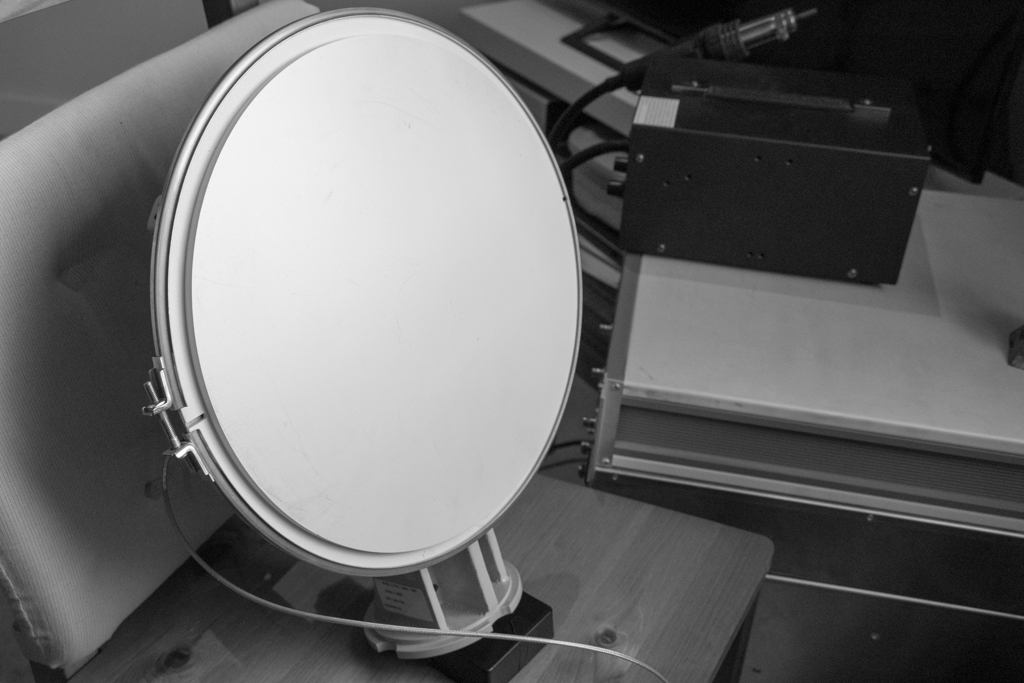
The downlink of QO-100 is on 10.5 GHz (X band). I received the signals using a downconverter from an LNB and a small parabolic antenna (30cm) placed on a chair pointing to the satellite through an open window. As the downconverter had a free-running oscillator without any temperature stabilization, you can hear that the receiving tone is not stable. Using a disciplined oscillator will be the next step. The record of the Beacon can be found here.
In the next step, I modified my LNB. I removed the internal crystal (25 MHz) and replaced it by an SMA connector. Then I used an arbitrary waveform generator that was disciplined to GPS (10 MHz clock) and injected the signal into the LNB.


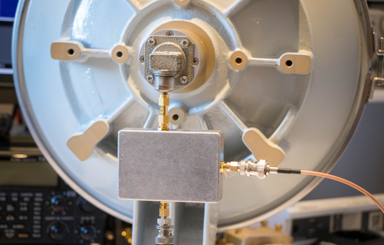
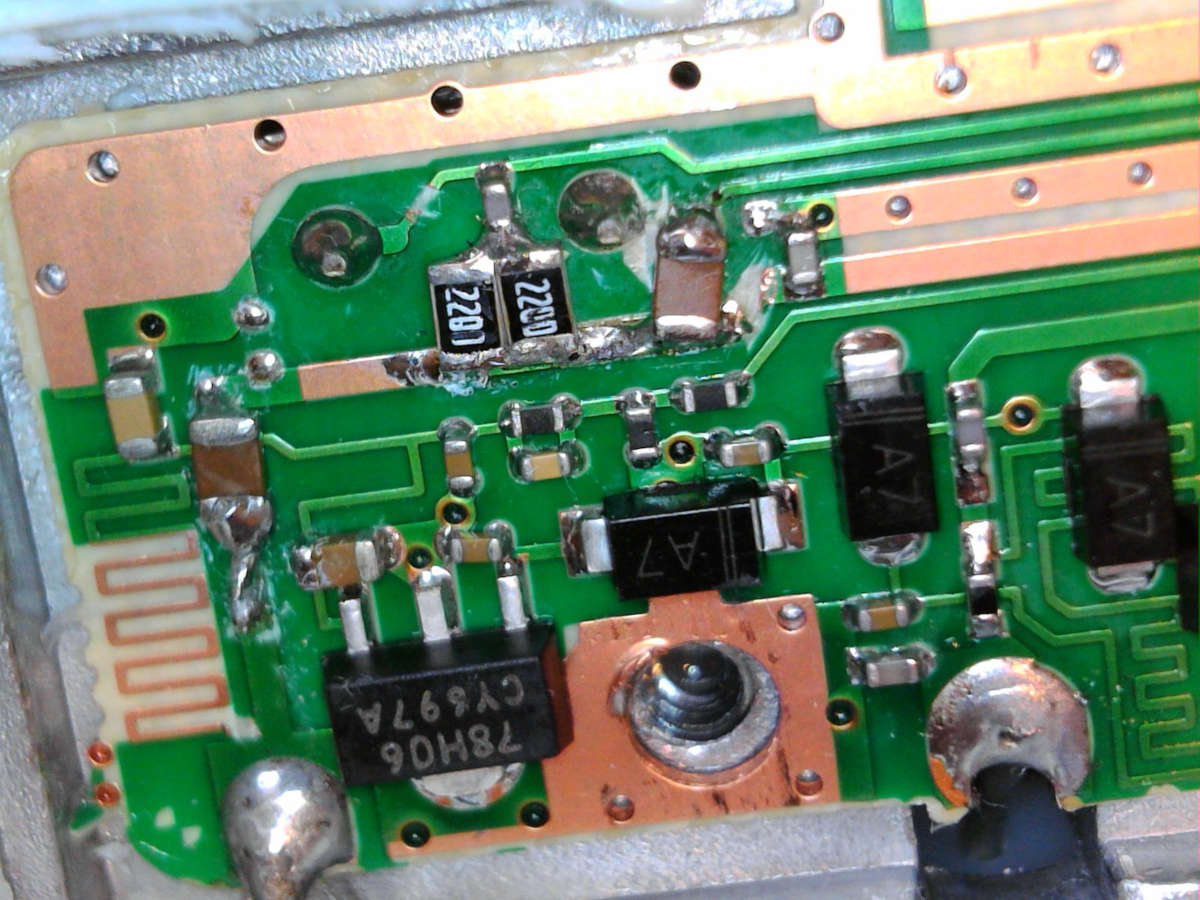
This solution worked significantly better in terms of frequency stability but I was not happy with the mechanical construction and with the RF path on X-band where an adaptor from circular waveguide to a rectangular waveguide was connected to an adaptor form rectangular waveguide to SMA connector. Then another SMA to SMA adaptor was used for connection of the LNB as can be seen in the picture above. This was the reason why I decided to modify Quad Octagon LNB based on this description. My modification (before and after) can be seen in the following photos.

Once the modification was finished I designed and 3D printed an adaptor for my dish. I cut the original horn antenna with a pipe cutter. The goal was to keep the front face of the circular waveguide as flat as possible. Then I glued the 3D printed adaptor to the LNB. The shape of the LNB's waveguide is slightly conical, so there is a small gap between the waveguide and the adaptor. Fortunately, it is on the side where the adaptor is not connected to the antenna, so it does not have any significant effect. The connection is rigid and the LNB can be connected to the dish antenna with four screws. So far I am happy with this setup.


PicoBalloon Challenge 2019
PicoBalloon Chalenge 2019 was held in Brno on Monday, 4th March and was organised by SOSA - Slovak organisation for space activities and Brno Observatory and Planetarium in cooperation with S.A.B. Aerospace and Czechinvest.
I noticed this competiton in January 2019 but my idea was to visit the observatory to see the teams and their radiosondes. My friend Vlada (OK1FET) sent me a message three weeks before the event that we could join the competition as he tried radiosondes in the past. We discussed the details a bit more but I found that Vlada had his radiosonde nearly prepared, so I decided to build my own radiosonde as well.
The idea was to trasmitt a morse signal (CW) on short waves once per 10 minutes and to use RBN (reverse beacons) for detection and monitoring. Even though the idea was simple, it was quite challenging to get everything done on time.
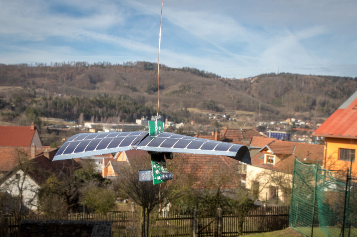
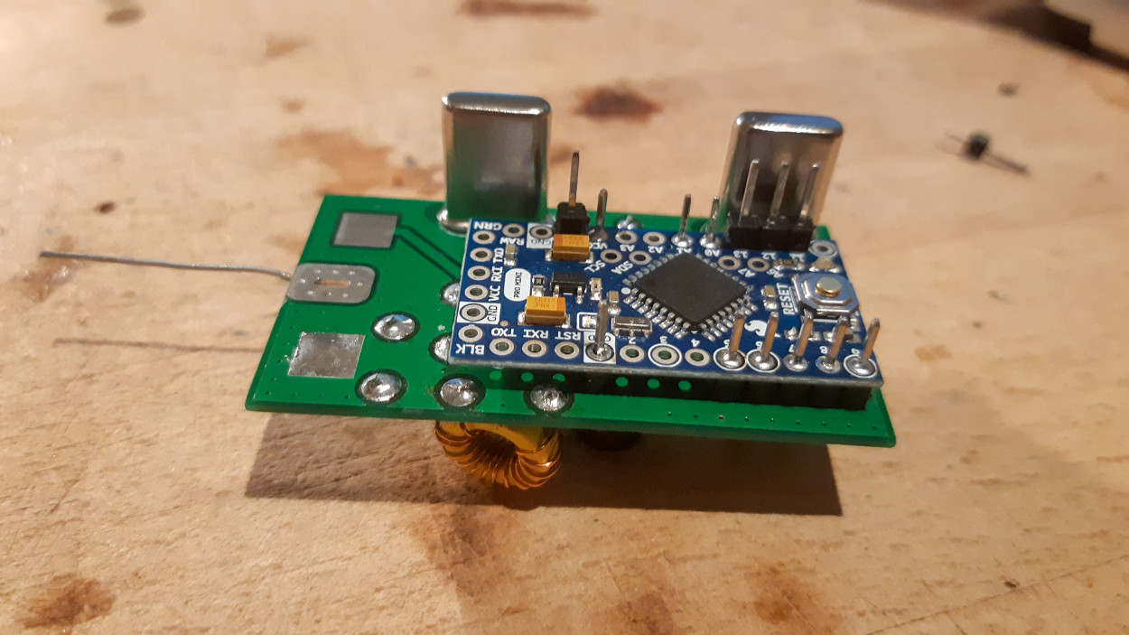
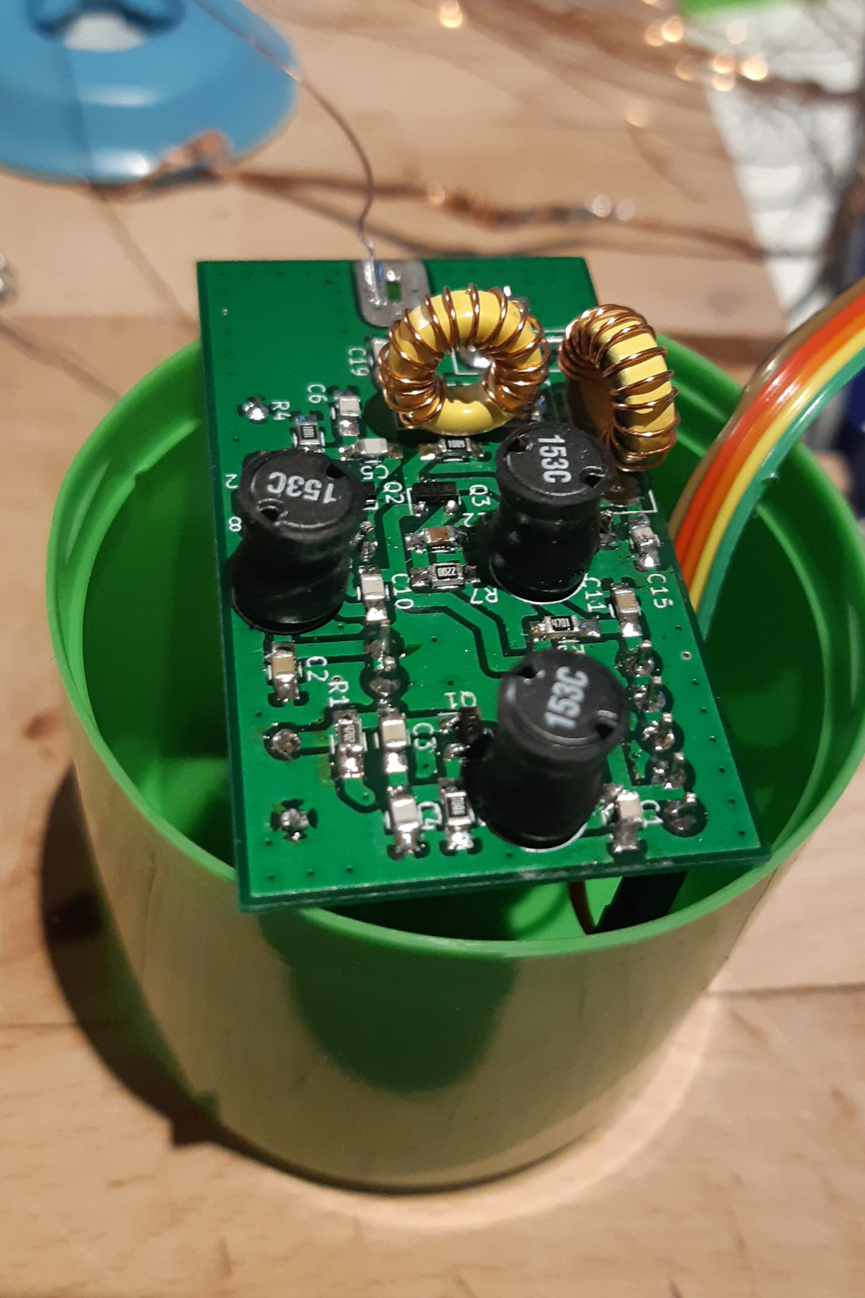
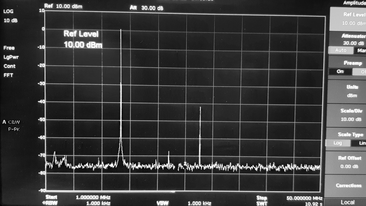
My radiosonde contained two switchable oscillators that worked at 7MHz and 14MHz, one small amplifier, low pass filter and a microcontroller. All of that was powered by solar pannels. When the PCB arrived and a prototype was working, I spent most of the remaining time reducing the unwanted harmonic signals (especially those which were not inside HAM bands) to make sure that my radiosonde does not produce any interference. This part was successful as can be seen from the measurements (the second harmonic was reduced by 40dB at 28MHz and the third harmonic was below the noise).
I finished both firmware and soldering at 10AM when some of the teams were probably at the observatory. I arrived at 12 o'clock. The official start (launch) was at 1PM. We were given some instructions, balloons with helium and we could go for launch. It was actually much more difficult than I expected due to the wind speed. I managed to break my antenna during the first attempt. Fortunately, Ondra (OK1CDJ) was very kind and lent me his soldering station, so I could fix that. I checked that everything worked and launched the balloon. I must say, it was a very stressfull launch. The radiosonde nearly hit a tree, hit a roof (unfortunately not as nearly :)) and finally gained some height.
Even though the reverse beacons haven't received any signal from my radiosonde yet, I really enjoyed the event, met some very nice people, learned new things both during the development and the event itself and I have a lot of new ideas for next year.
And finally, a big thank you to the organizers of this event and I hope that we will see each other next year again.

RCWL-0516 Microwave Motion Detector
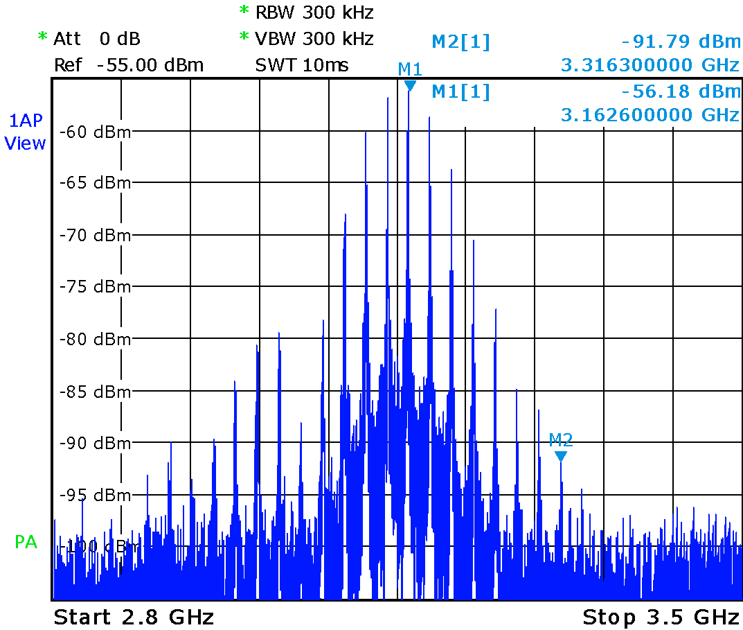
I found this module in our local electronic components store. The module was called Microwave radar motion detector which attracted my attention, so I decided to buy it (£2) and to perform some tests. I only connected pins VIN (5V), GND and OUT. When the chip detects a movement, pin OUT changes its state form logic low (0V) to logic high (3.3V). I wrote a piece of code to show the state of the sensor using an LCD display and an LED diode. (A short video presenting the motion detection can be found here: RCWL-0516 Microwave Sensor.) I noticed that the sensor is very sensitive as when I was close enough, my breathing was modulating the frequency response of the module (due to reflections). Furthermore, I meassured the spectrum. I used a short probe at a distance of about 5 - 10 cm away from the sensor. The measurements can be seen in the following figures.

The measured spectrum (near-field) can be seen in the following figures. The first measurement was made at home, the second one was taken at the university as I am a bit limited with the frequency range in this case.

I have found two nice videos explaining how such sensors work.

