--- Welcome to RFsignal.eu ---
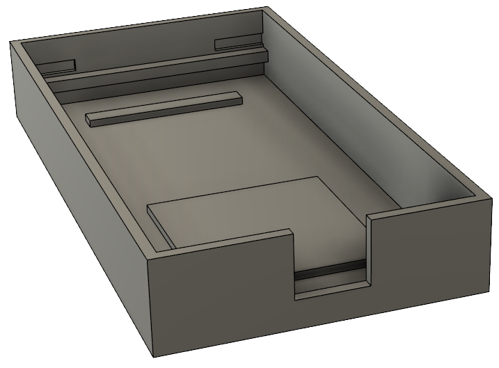
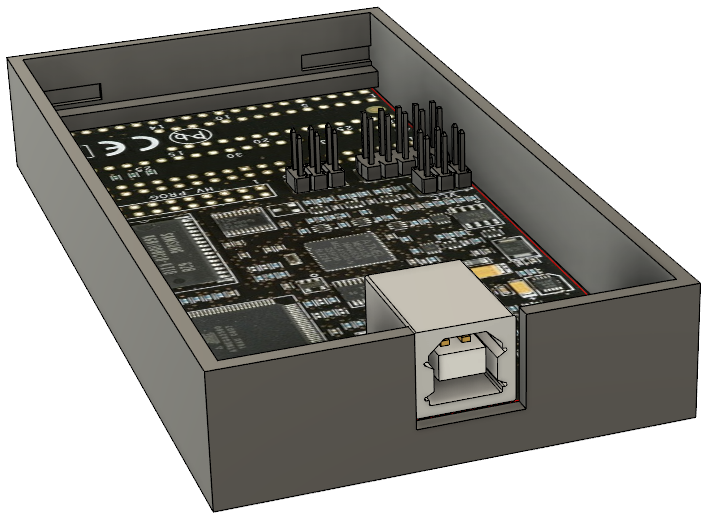
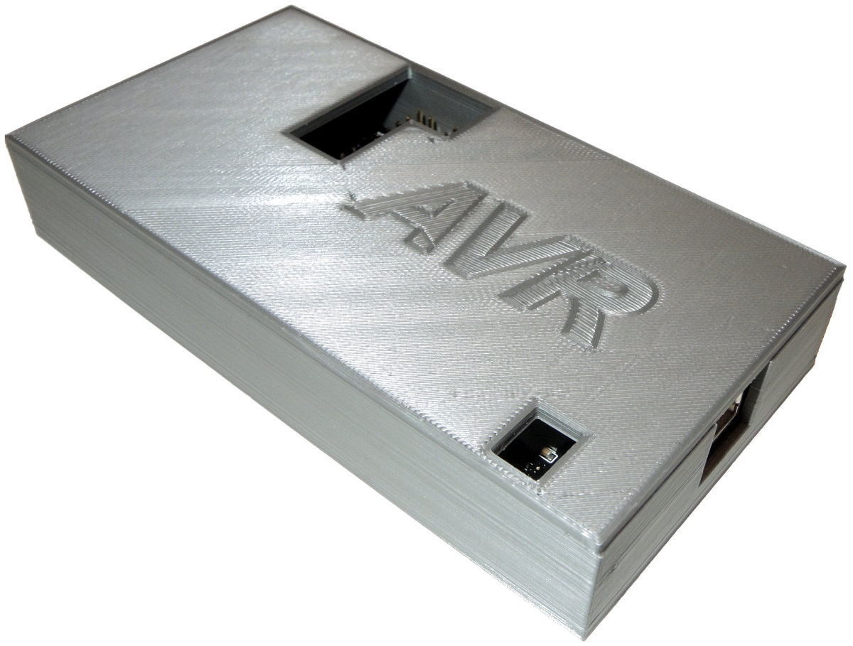
Box for Atmel AVR Dragon - Design and 3D print
During the last weekend I designed and printed a new box for my Dragon programmer. This programmer supports all programming modes for the Atmel AVR device family such as SPI, JTAG, PDI, high voltage serial programming, parallel programming, and aWire.
I used specialist software for 3D modelling (Fusion 360 by Autodesk).

 |
 |
 |
 |
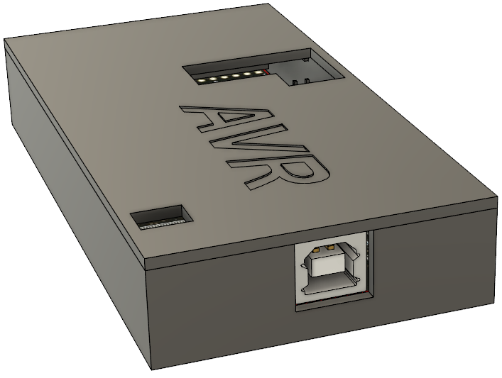
And finally... The result - 3D printed Box
Fun With LCD Alphanumeric Display
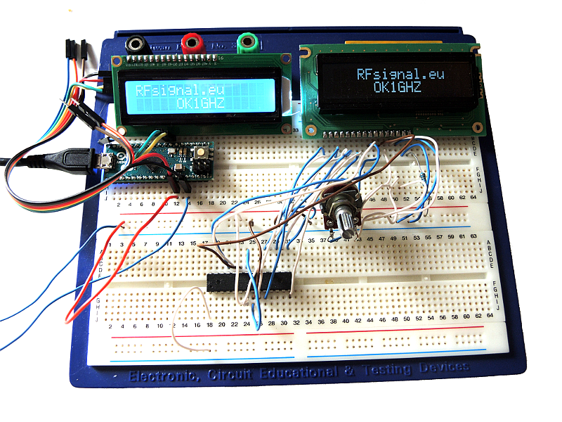
Today I did the same thing twice. Firstly, a parallel bus is used for controlling a display. In the following picture you can see Atmel microprocessor ATmega88PA with LCD display Winstar WH1602A-TTI-ET + AVR Dragon Debugger.

Secondly, I tried to control an LCD display via I2C bus with Arduino micro. Both circuits can be seen in the following picture.
HF Multi-Band Mobile Radio Communication Antenna
I have made a new antenna for my mobile / portable HAM radio activity. This antenna works at 3.5, 7, 10, 14 and 21MHz. A short video of DL3DL/P activating WFF (World Flora Fauna) DLFF-128 at 7MHz can be seen here.


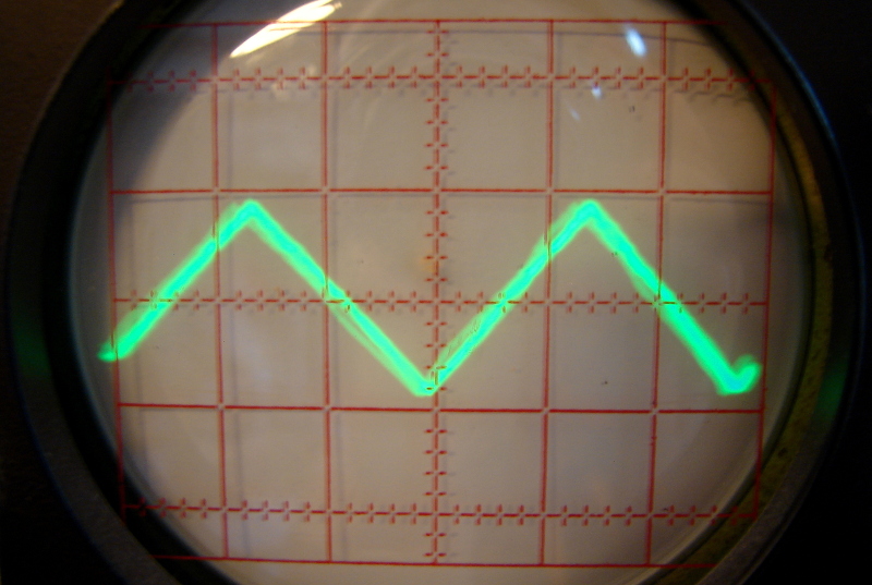
Function Generator (Atmel ATmega88 + D/A Converter)
This is one of my older projects written in assembler. The output signal is generated by ATmega88 with D/A converter DAC0832LCN.


GPS Frequency Reference - Remotely Controled GPS Module via UART
Modules NEO by U-blox are very popular GNSS receivers in these days. I have bought NEO-7M GPS/GLONASS module. A synchronized time signal can be also found on the board and you can control the frequency as well as the duty-cycle via a serial port (3.3V logic). The output signal can be used e.g. for disciplined oscillators. All important information about this module is in its datasheet. A disadvantage is that the datasheet is very complex.
I have written a piece of software in Python with WX graphical interface for my experiments. This software can also run on Raspberry Pi and it allows to control the output frequency and the duty-cycle in locked and unlocked mode via UART. If I want to use a different device e.g. a microcontroller I can just use the code generated by the application (the last text box in the form) for UART request so the application is still useful.
I have also placed the module into a small plastic box as you can see in the following images.
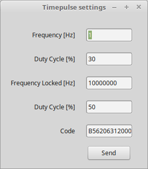
Developed application
1. GNSS module with an antenna, mechanical construction
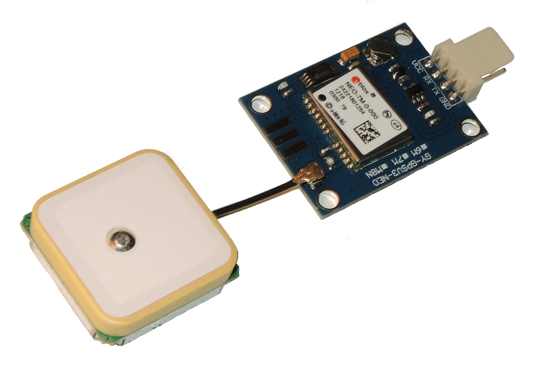
GNSS Module U-blox NEO-7M

DC input, RS-232, LED indicating the output frequency and BNC connector - the output signal
2. RS-232 communication test, measurement
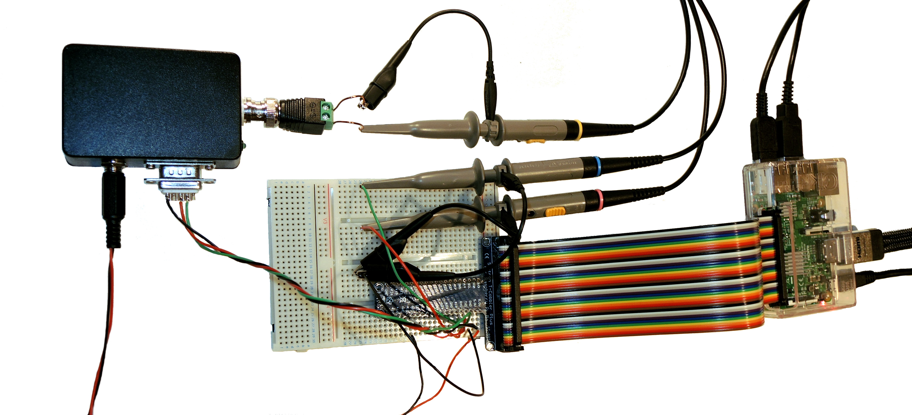
Controlling the module with my application and Raspberry Pi.

The output frequency (Yellow) is changing from 1Hz to 10Hz after my request (Purple)
Purple - RS-232 (TX) - Request sent via the new application
Blue - RS-232 (RX) shows the received NMEA messages
3. Results - output signal measurement
For presenting the measured data I use my software connected to an oscilloscope via LXI bus which I have already presented here.
The time pulse signal is connected to a resistor and a LED diode on the board. I removed both the LED diode and the resistor, so the BNC connector was connected directly to the output. The following figures present the measured time pulse signal:
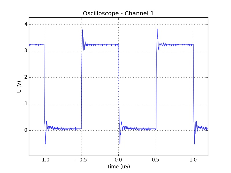
a) Output frequency: 10 kHz

b) Output frequency: 100 kHz
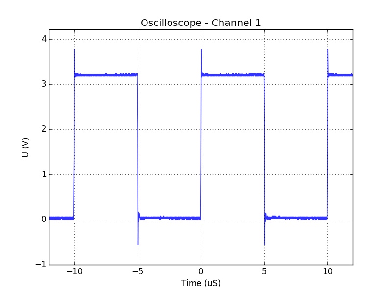
c) Output frequency: 1 MHz