--- Welcome to RFsignal.eu ---
Impedance Transformer 1:49 for EFHW Dipole Antenna
This article presents my construction of an impedance transformer designed for an end-fed half-wave dipole (EFHW). The advantage of an EFHW dipole is that it does not have to be fed in the centre as well as multi-band operation. The disadvantage of such a configuration is the high impedance (thousands of Ohms) at the feeding point. Unfortunately, in comparison with the centre-fed dipole and its well-defined impedance, the impedance of the EFHW antenna can be somewhere between 2000Ω to 5000Ω. There are several options on how to feed this kind of antenna. Parallel resonation circuits which are tuned for a specific band are very popular. The other solution is a broadband transformer based on an auto-transformer with an impedance ratio of 1:49 or 1:64. This time, I tried to build two 1:49 transformers based on an FT240-43 ferrite core. Two constructions with one and two ferrite cores were compared. For both cases, 2 turns on the primary side and 14 turns on the secondary side of the transformer were used. A capacitor improving the characteristics at the higher bands was connected to the primary winding. It was made of coaxial cable RG178. Firstly, I tried several options with standard ceramic capacitors as well as variable trimmer capacitors and based on the measured response I determined the best value. Then I cut the coaxial cable to the length that provided roughly the same capacitance and carefully shorted the coaxial cable piece by piece to obtain optimal performance. In my case, the version with one core provided best results when 100pF was used and the version with two cores provided best results at 200pF. Furthermore, I added a switch to the two core design which allows the transformer sides to be galvanically isolated. It provides the option to choose between a wire and a coaxial cable as a counterpoise wire. Please find the images and measurements below.


Measurement setup (choosing the correct value of the capacitor):

As can be seen the transformer with one core was more broadband in comparison with the two core design. Two core design provides better reflection coefficient at 3.5 and 5MHz.

If you prefer SWR instead of |S11|, you will find the following figure useful.

Furthermore, the transformers were connected back to back and transmission (S21) was measured. As the transformers were not identical, the results are only informative. On the other hand, they had overlapping bands, so one can get the idea of the losses.


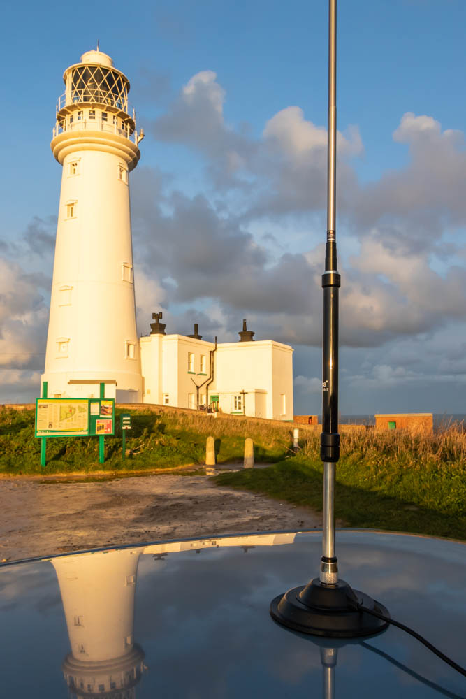
Multi-Band Portable Vertical Antenna (HF + VHF) Komunica HF-PRO-2-PLUS-T
A typical centre-fed λ/2 dipole antenna has an impedance of Zd = (73+j42.5)Ω. To cancel the inductive reactance, the length of the dipole needs to be reduced. It will also affect the resistive impedance but the effect is not significant as the reactance curve is much steeper in comparison with the resistive impedance in this region. When only one arm of the dipole antenna is placed perpendicularl to the ground plane, a quarter-wavelength (monopole) vertical antenna is made. In an ideal case, the impedance of the monopole antenna can be calculated as Zv = 0.5*Zd and approximately 36Ω can be expected at resonance. When the size of the λ/4 vertical antenna needs to be reduced, there are two main techniques based on inductive and capacitive loading which can compensate for the low radiation resistance and high capacitive reactance. These two techniques can also be combined. The negative effect of shortening is reducing the efficiency of the antenna as well as narrow bandwidth due to the high Q factor. Even though the loading coil placed at the base of the antenna is not the best option in terms of efficiency, it is a very convenient place for tuning. When the length of the whip is constant, for multi-band operation the inductance of the loading coil needs to be changed appropriately.
I have already presented this homemade antenna where the inductance can be changed in steps. Then the fine-tuning was performed by changing the length of the top telescopic section of the antenna. This configuration works well but in many cases is not practical especially when the antenna is placed on the roof of a car, so the antenna must be dismounted when the band needs to be changed or when the change from SSB to CW segment of a band is required. Also, the efficiency is given by the length of the antenna, so the best choice is to keep the antenna at its maximum length. Therefore, I was looking for other options and mechanical realisations and I found an antenna (Komunica HF-PRO-2-PLUS-T) with a continuously tunable coil and a telescopic whip. The antenna came with the main tunable coil, an extending coil for 80m band and a telescopic whip. The length of the antenna is only 30cm when disassembled and 2.7m when extended. So far I am very happy with it. I am not sure if the antenna is water-resistant. I think it is better to avoid such weather conditions when possible. The antenna can be tuned only by shifting the coil which makes the whole tuning process significantly easier and faster.
GNSS Sector Antenna
I have written an article published in IEEE Antennas and Wireless Propagation Letters presenting GNSS Sector Antenna for Interference Mitigation and Localization using High-Impedance Reflector.
Abstract: There are many applications where the reception of global navigation satellite system (GNSS) signals is crucial. In such cases, the capability to reduce the interference (both unintentional or hostile) is critical. The proposed sector antenna offers a stable radiation pattern with no beam steering across the frequency band and good impedance matching. It also benefits from a high impedance reflector, which allows the antenna to provide broadband operation and low-profile compact geometry. Furthermore, seven of these sector antennas were placed in a heptagonal shape and combined with a broadband crossed dipole. As a result, the designed antenna system can reduce vertically polarized interference by approximately 45 dB in the required directions.
The article can be found here.

Magnetic Loop Antenna
This article presents my magnetic loop antenna (MLA). The antenna covers 7 MHz, 10 MHz and 14 MHz HAM radio bands. Magnetic loop antennas are based on a resonation circuit made of a loop and a tunable capacitor. In my case, the diameter of the loop (coil of two turns) was 52 cm and a butterfly air variable capacitor (12 - 125 pF, 3 kV) was used. The antenna can be tuned by hand but there is high voltage at the capacitor when transmitting, so the tuning knob must be properly isolated. The resonation frequency can be shifted when the hand is placed near the antenna, also due to the high Q of the antenna the resonation is very sharp and it can be difficult to fine-tune the MLA. Therefore, I decided to build my MLA with a motor. For precise positioning, I chose a stepper motor with a gear unit (100:1). As I wanted to avoid an external cable from the antenna to the control unit, a Bluetooth connection was used. The control unit features an LCD touch screen. The firmware for it was written in AVR C and an interesting fact is that I wrote the firmware in a way that the same control board based on ATmega 2560 can be used for both the antenna and the control unit. It allowed me to debug the entire system with just one board. I have already made many contacts around Europe from my flat with this antenna. Usually, 5 - 10 W is sufficient for CW contacts. I have a lot of ideas for further improvements, so I will update this article once I have new modifications.
A short video can be found here (Vimeo).
OK-OM DX Contest 2020 (YouTube)


USBasp with Atmel Studio 7
This short article presents my setup of Atmel Studio 7 for USBasp programmer. USBasp is a simple low-cost programmer that does not offer any advanced features such as on-chip debugging. On the other hand, the cost of this programmer is significantly lower in comparison with Atmel-supplied debuggers such as Atmel-ICE. USBasp can be added into Atmel Studio as an external tool. The following steps present the installation process.
1. Plug in your USBasp.

2. Install libusbK driver using Zadig software as presented in the following picture. (If you cannot see USBasp device you might need to click on Options -> List All Devices.)

2. Download AVRdude http://download.savannah.gnu.org/releases/avrdude/?C=M&O=D (in my case avrdude-6.3-mingw32.zip and avrdude-doc-6.3.pdf).
3. Unzip the downloaded file to a chosen folder.
4. Open Atmel Studio and click on Tools -> External Tools as shown in the screenshot.

5. Choose a title you like.
6. Command is the path to your downloaded (unzipped) avrdude.exe file.
7. Field Arguments is specific for your type of microcontroller. In my case I used ATmega2560 (m2560) . More information can be found in avrdude-doc-6.3.pdf file.
avrdude -c usbasp -p m2560 -U flash:w:$(ProjectDir)Debug\$(TargetName).hex:i
8. $(ProjectDir) sets the Initial directory as a project directory.
9. Check "Use Output Window" for status messages of avrdude.exe.

10. Write a simple code and click on Build -> Build Solution (F7). The following code blinks an LED on the MEGA 2560 board.
11. Press Tools -> USBasp to program your microcontroller. Good luck!
