Gw Instek GPD-3303: USB remote control repair
I needed a laboratory power supply for my experiments, so I decided to buy GW Instek GPD-3303D. It is a power supply with 2 independent channels (0-32V) and one fixed channel where the voltage can be set to 2.5, 3.3 or 5V. Furthermore, it can be controlled via USB port remotely. I really looked forward to do some first tests. What a surprise when I found that the power supply does not communicate via the USB port! After some time I discovered that the communication from PC to power supply is probably OK but the power supply doesn't send any data back.

In the end I tried to fix that. The USB port of the power supply is connected to an interface board (USB-UART), so I checked this board first to be sure that there are no shortcuts and so on. Unfortunately, it looked ok. It would be too easy. :)
I managed to find a service manual. The power supply uses PIC 18F85J10 (3.3V logic), so I tried to use my Raspberry Pi which has 3.3V UART on its GPIO bus. (It mans that I didn't have to use the original interface board (USB-UART) and I could communicate with the main processor of the power supply directly.) For this purpose I wrote a simple program in Python for testing the communication and it worked. Secondly, I tried the same thing with my own USB-UART module (CP2102) which I ordered for this test. Fortunately, it also worked well. (I used Linux Mint)

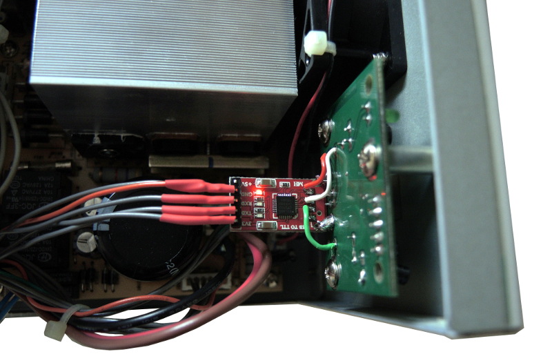
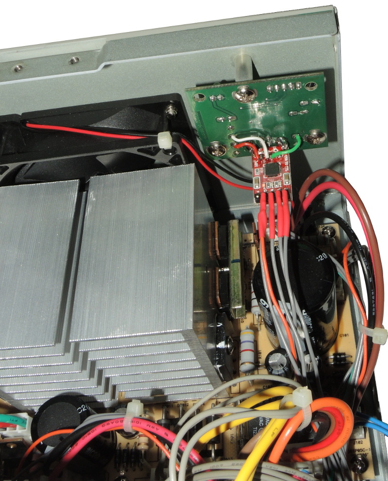
I still was not sure where the problem exactly was so I decided to replace the old board with my CP2102 USB-UART module. The advantage of this module is that it provides 3.3V logic and no external resistors are required.
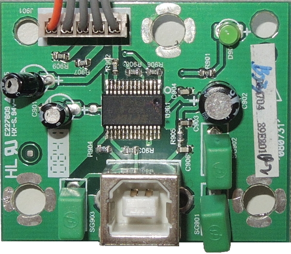
So I modified the interface board and used only the USB connector. You can see in the following picture that I removed some resistors and capacitors.

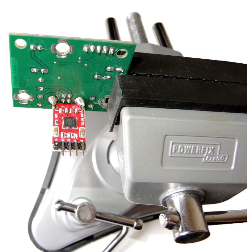
Then I modified the CP2102 module and joined both boards together.
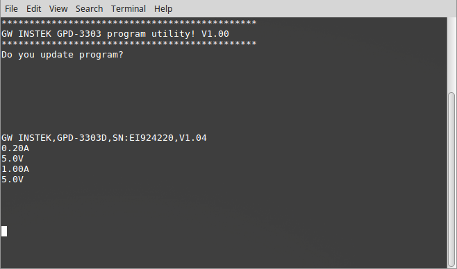
It works well and I can read data from the power source without any problems as can be seen in the terminal (following picture). The first message in the terminal is shown every time when the power source is switched on. Secondly, I used commands to get ID of the power supply and set values of both channels. (First channel was set to 0.2A, 5V and the second one was set to 1A and 5V). I am very happy that it works and I am going to write a piece of software to control this power supply from PC.
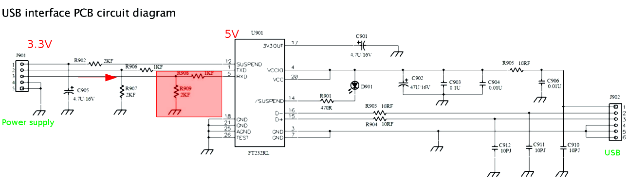
For the first experiments I used my old PC with Windows 8.1. It seems that the provided software Power GPD by Gw Instek doesn't work with this PC properly. Therefore it was hard to find where the problem was as there could be a problem in the provided software, in my own code or in the hardware. In my opinion one of the reasons why the communication didn't work are resistors R908 and R909 on the original interface board (USB-UART) as presented in the following schematic. You can let me know if you agree with me or what is your opinion.
The second thing I do not enjoy is the response of the power supply when the voltage and current are set via the two knobs. The reason is that the regulation is non-linear and it has an "accelerometer", and in my opinion, it is too sensitive. I might understand using this function for the Coarse mode. Unfortunately, this function is activated also in the Fine mode. So you are setting 3.4V, 3.5V, 4.0V and all of a sudden jump to 15.0V! This is a great function for those people who enjoy smoke in their laboratory. :)
(This problem might be fixed in a newer firmware. It can be seen in the terminal that my version is 1.04)